Straight pull bolt actions balance cycling speed against mechanical lockup
A modular straight pull mechanism converts linear manual force into rotary locking, offering smoother cycling while preserving standard receiver dimensions and trigger components.

Traditional bolt-action rifles demand a four-stage manual sequence from the shooter. To chamber a fresh cartridge, a user must rotate a bolt handle upward, pull the assembly rearward, push it forward, and turn it downward to lock the breech against combustion pressure. That multi-axis sequence keeps the locked breech secure against tens of thousands of pounds of chamber pressure, but it disrupts the shooter's aim and slows consecutive shots.
Straight-pull bolt mechanisms attempt to reduce that physical cycle to a single backward-and-forward motion. By eliminating the manual rotational step, a straight-pull layout allows the shooter to cycle the firearm rapidly without twisting their hand or breaking their visual alignment with the target. Yet translating pure linear pulling force into rotary locking has historically required intricate internal geometries that complicate manufacturing and limit compatibility with widely available modular parts.
Most commercial straight-pull firearms remain proprietary platforms with narrow aftermarket support and restricted caliber selections.1 Shooters looking to swap calibers, customize triggers, or attach modern sighting systems frequently encounter specialized receivers that do not interface with standardized firearm furniture or magazines. A mechanical configuration that delivers straight-pull speed while preserving the geometry of modern modular receivers could widen the accessibility of manual precision platforms.
Before any mechanical assembly can operate safely, the firearm must complete an unbroken chain of mechanical handoffs. A firing pin strikes a chambered cartridge, triggering propellant combustion that drives the projectile down the bore while high pressure pushes back against the bolt face. The bolt must remain rigidly locked to the barrel until internal pressures drop to safe levels. Once chamber pressure dissipates, the shooter pulls the operating handle straight back, forcing internal cams to twist the bolt out of its locked recess, extract the spent cartridge case, and fling it clear of the receiver. As the shooter pushes the handle forward, the assembly strips a fresh cartridge from the magazine, pushes it up an incline into the chamber, and cams the bolt back into locked battery.
A patent granted to inventor Matthew Earl Herd outlines an operating system that aims to resolve these constraints through an integrated bolt carrier assembly. The document, titled Firearm and published on August 25, 2026, details a straight-pull mechanism engineered to fit within an upper receiver while maintaining compatibility with conventional lower receiver components. Herd's filing describes an arrangement where linear manual input directly drives rotational lockup through dedicated internal guide and cam surfaces.1
How does linear motion produce rotary locking in a straight pull bolt?
Linear motion generates bolt rotation by routing a cam follower through guided tracks between the moving carrier and the rotating bolt head. In the design documented by Herd, the bolt carrier assembly sits inside a longitudinal passageway of an upper receiver and comprises four primary components: a bolt carrier, a rotating bolt, a follower element, and a manual operating component.1 As the bolt carrier translates along the longitudinal axis of the upper receiver, the bolt itself is received within the carrier and is configured to rotate about that same longitudinal axis.1
The transformation from straight pull to rotational locking relies on the follower element engaging both the rotating bolt and a cam feature machined into the bolt carrier.1 The upper receiver passageway features a main portion alongside a distinct cam portion with first and second guiding surfaces.1 When the bolt carrier rests in its forward position, the follower element is constrained from rotating about the longitudinal axis by these receiver surfaces.1 As the carrier assembly moves toward its locked position, the follower element travels along the carrier's cam track, compelling the bolt to twist into rigid engagement with a barrel extension at the breech end.1
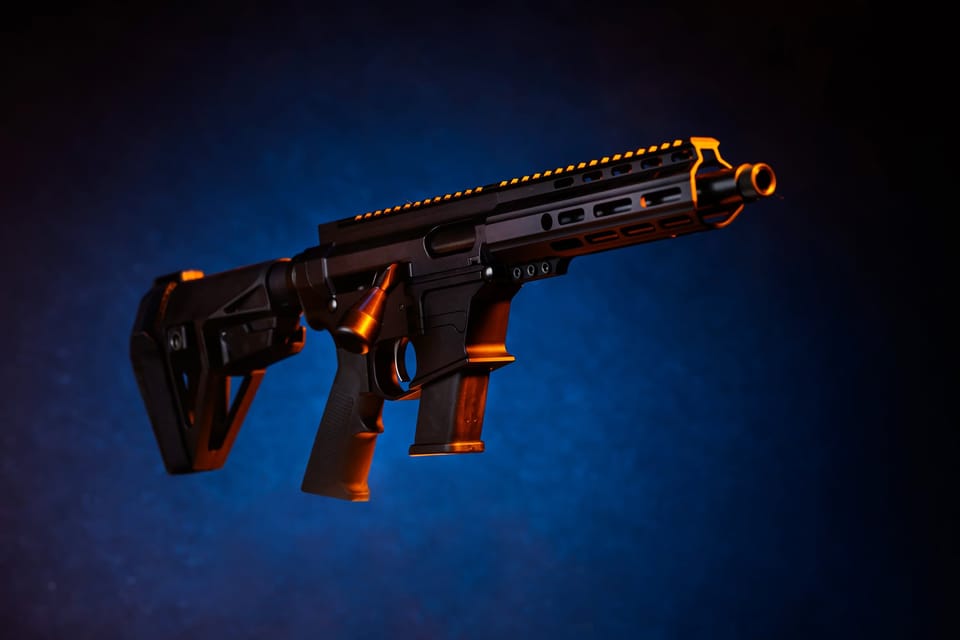
This geometric division of labor allows the shooter to apply purely longitudinal force while the internal mechanism executes the rotary lock. Matthew said in response to questions from Primary that "the follower element is used to rotate the bolt relative to the carrier as the carrier is moved into battery to chamber a round." Matthew explained that "this is the component that allows us to rotate the bolt while moving the bolt handle linearly." The patent specification outlines a sequence of operation beginning when the carrier assembly is positioned so the follower element engages the cam surfaces of the receiver passageway while the operating component contacts a first guide surface.1 Translating the carrier rearward slides the assembly along the guide surface, releasing the rotational lock as the follower tracks the cam pathway.1 Reversing the stroke drives the carrier forward, forcing the follower along the cam feature to rotate the bolt lugs into full lockup without requiring any twisting input from the user.1
What keeps the mechanism aligned during rapid cycling?
Mechanical alignment is maintained by an operating component that interfaces simultaneously with both the upper receiver and the lower receiver.1 Herd's specification discloses that this operating component engages the bolt carrier and contacts a first guide surface that directly prevents the bolt carrier from rotating during travel.1 By anchoring against the guide surface, the carrier is held strictly along its translational path, ensuring that only the forward bolt head undergoes rotational movement while the surrounding body stays stable.
The physical interface between the operating handle and the carrier also incorporates a perpendicular coupling geometry. According to the patent disclosure, the operating component is slidably coupled to the bolt carrier along a coupling direction that runs perpendicular to the longitudinal axis of the firearm.1 The upper receiver contains a slot extending from its internal passageway to an outer surface, through which the operating component detachably couples to the carrier.1 This perpendicular arrangement allows a shooter to remove or install the operating component during disassembly without requiring specialized tools or complex disassembly pins.1
Maintaining that perpendicular connection under harsh firing conditions required strict fabrication limits. Matthew told Primary that "one key design criteria that I set early on in the development process was tool-free takedown of the firearm." Matthew noted that "this meant that it was critical to develop a coupling method for the bolt handle that ensured that the bolt handle was easy to intentionally remove, but impossible to accidentally remove." Achieving that standard presented practical manufacturing challenges. Matthew stated that "the biggest hurdle was making sure that the bolt handle was coupled to the bolt carrier so that it has zero free play." Matthew added that "this required tight tolerance machining to ensure that both components remain securely connected," and pointed out that "the arrangement of the upper and lower receiver make it impossible for the bolt handle to come off unintentionally."
To maintain the action securely closed prior to firing, the upper receiver assembly incorporates a spring-biased retention detent.1 The filing specifies a detent, a spring, and a retaining pin mounted within the upper receiver assembly, with the detent biased downward to engage the bolt carrier assembly and hold the firearm in battery.1 This detent creates a defined mechanical threshold that keeps the bolt fully closed against inadvertent movement, yet yields cleanly when the shooter exerts deliberate manual force on the operating component. Addressing whether dynamic recoil forces could overcome this restraint, Matthew told Primary that "no amount of chamber pressure will cause the bolt to unlock prematurely." Matthew explained that "while the carrier can move slightly due to reaction forces from firing, pressure will already have dropped to a safe level before this can occur." Matthew observed that "the movement of the carrier is analogous to the operation mechanism for many Benelli shotguns, except that our firearms do not have enough recoil force to unlock the bolt," emphasizing that "the bolt remains locked until pressures have dropped to safe levels."
How does the architecture handle cartridge feeding and case ejection?
Cartridge feeding relies on a dedicated feed insert that coordinates with a secondary ramp to guide ammunition from the magazine into the chamber.1 In Herd's arrangement, a lower receiver houses a magazine well that receives a magazine containing a spring, a follower, and a stack of cartridges biased against feed lips.1 The upper receiver carries the feed insert, which features a clearance path permitting cartridge passage and a secondary ramp positioned to direct incoming cartridges toward a primary feed ramp formed on the barrel extension.1
This dual-ramp architecture helps prevent feeding jams across diverse bullet profiles and cartridge dimensions. Matthew told Primary that "the secondary feed insert is used to allow more complicated geometry than would be provided by a typical M4 style feed ramp formed in the M4 rifle's upper receiver." Matthew noted that "this is required to facilitate feeding of short, large diameter, cartridges." Matthew explained that "most pistol cartridges are short and stubby, which makes feeding a significant challenge." In particular, Matthew added, "commonly available pistol magazines cannot feed a rotating bolt without significant work on the feed ramp and magazine positioning to make them feed reliably." By comparison, Matthew pointed out that "rifle cartridges are far longer and more slender, which significantly reduces their feeding challenges."
The barrel assembly includes a barrel extending from a breech end with a chamber to a muzzle end, with the barrel extension coupled to the breech to engage the rotating bolt. As the forward-moving bolt strips the top cartridge from the magazine, the secondary ramp on the feed insert catches the cartridge nose and directs it smoothly toward the barrel extension's feed ramp, ensuring reliable alignment into the chamber bore whether using smoothbore or rifled barrels.
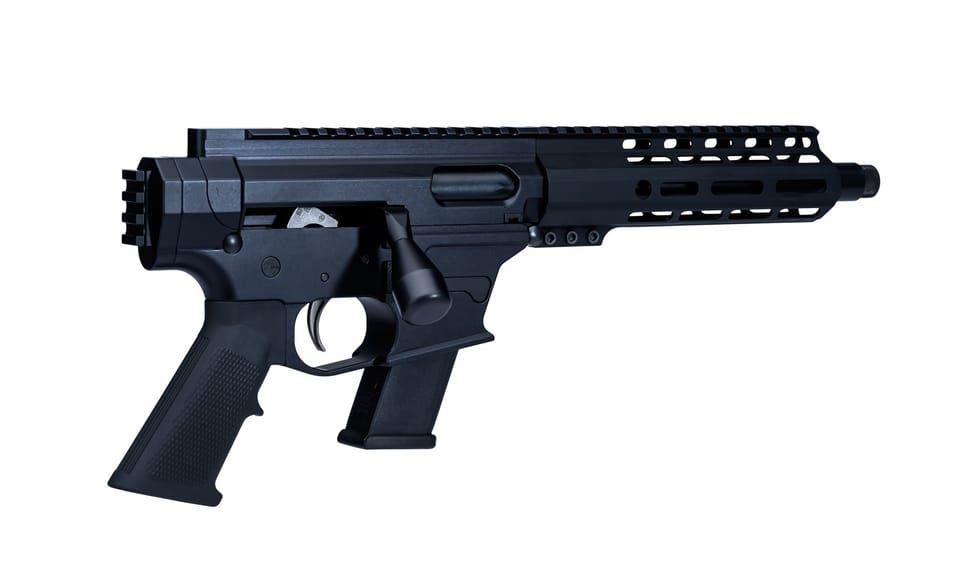
Case ejection is accomplished by a fixed ejector that interfaces directly through coordinated channels in the moving action. The patent describes an ejector secured to the upper receiver by multiple fasteners, with an ejection portion extending directly into the internal receiver passageway.1 Both the bolt and the bolt carrier feature specialized slots configured to pass around this ejection portion as the assembly translates between its forward and rearward positions.1 When a fired cartridge case is extracted from the chamber, the rearward translation brings the cartridge rim against the stationary ejector projection, flipping the spent brass through an ejection port without relying on spring-loaded plunger ejectors in the bolt face.
What can a patent filing reveal about practical performance?
A patent specification is a legal description of mechanical structure rather than an empirical assessment of real-world shooting performance. Herd's document describes an operating concept, detailing component geometry, assembly steps, and mechanical interfaces, but it presents no experimental measurements of cycling speed, extraction reliability, or mechanical endurance.1 The text contains no test data comparing lockup strength against standard turn-bolt actions, nor does it quantify manufacturing tolerances or production costs. The filing establishes the intended fit and mechanical interaction of the components, leaving performance under sustained field use or harsh environmental conditions to future testing.
The filing also leaves open which manufacturing processes and metallurgy would be necessary to withstand sustained operating pressures. The specification notes that while the exemplary embodiment is configured as a straight-pull rifle, the operating principles could be adapted to bolt-action pistols, semi-automatic rifles, automatic rifles, or other projectile launching devices. The document does not describe physical prototypes or laboratory test firings, meaning questions regarding component wear, dirt sensitivity, and thermal expansion during rapid firing remain unanswered by the public disclosure.1
Physical testing has nevertheless proceeded outside the text of the patent filing. Disputing the implication that physical hardware had not been evaluated, Matthew told Primary that "we've run the Baza family of firearms through many thousands of rounds during testing, demonstration, and the like." Matthew reported that "the key issue that we have observed is lack of lubrication." Matthew explained that "carbon fouling plus a lack of lubrication will increase the failure rate of any firearm." In evaluating reliability, Matthew noted that "extraction is not particularly affected by carbon fouling, but eventually the gun will begin to suffer feed issues if it is insufficiently lubricated." Matthew concluded that "on the whole, our tests have revealed that the guns are at least on par with other bolt action designs in terms of reliability."
Handling extraction pressures presents an ongoing design boundary as the mechanism expands to larger ammunition calibers. Matthew told Primary that "our current products using this technology are chambered in pistol cartridges." Matthew explained that "this means that the cases are not generally subject to as much pressure as would be used in traditional rifle cartridges, allowing easier extraction." Looking ahead, Matthew stated that "we do plan to develop variants using rifle cartridges in the future," though Matthew acknowledged that "testing on those chamberings remain pending." In the absence of a conventional high-leverage bolt handle, Matthew said that "the unlocking of the action is aided by the time between firing of the cartridge and movement of the action." Matthew pointed out that "this gives the pressures within the chamber time to subside." Matthew added that "the cartridge case remains expanded, but will relax somewhat as heat transfers from the cartridge case into the barrel," noting that "these two factors are expected to make for relatively low force extraction," while confirming that "testing will soon tell us whether the theory is correct!"
Modularity across conventional firearm components represents a central objective of the disclosed architecture. The lower receiver assembly described in Herd's filing mirrors standard modular lower receivers, incorporating a fire control group pocket that accepts a trigger assembly consisting of a trigger, hammer, safety, disconnector, pins, and springs.1 The lower receiver connects to the upper receiver assembly using front and rear takedown pins secured by spring-loaded detents, allowing standard field stripping by pivoting the receivers apart.
The design further accommodates standard stock assemblies and accessory systems without requiring specialized furniture. Herd notes that the lower receiver receives a stock assembly comprising a buffer tube threaded into the receiver, a retainer plate, a retainer nut, and an adjustable stock that slides along the buffer tube to adjust length of pull. Accessory mounting is handled by an upper receiver rail that aligns with a rail on the hand guard, providing an unbroken platform for iron sights, telescopes, optical devices, lights, or imaging equipment clamped over the barrel assembly.1
Whether Herd's straight-pull architecture reaches widespread commercial production depends on subsequent prototype validation, tooling development, and market adoption. For gunsmiths and precision rifle shooters, the concept illustrates how thoughtful mechanical partitioning can integrate straight-pull cycling into familiar modular lower receivers. If the design transitions from patent diagrams to commercial hardware, independent testing will determine whether its internal camming surfaces deliver the cycling speed and mechanical durability that manual action shooters expect.
The record
53 sentences trace to 1 source and 1 contributor.
- 1 Firearm See the source
- 2 Contribution — Matthew Earl Herd 31 statements added to this article
Other consulted pages1 page
shootingnewsweekly.com1 page
akosarms.com3 pages
eureka.patsnap.com1 page
patents.google.com1 page
Article history
-
Published 18 Nov 2026, 18:11Assembled by the Primary desk from 1 source · 1 contributor · 53 cited sentences
-
Matthew Earl Herd, patent granted to inventor
- Go to the sentence: As the carrier assembly moves toward its locked position, the follower element travels along the carrier's cam track, compelling the bolt to twist into rigid engagement with a barrel extension at the breech end.
- Go to the sentence: Matthew said in response to questions from Primary that "the follower element is used to rotate the bolt relative to the carrier as the carrier is moved into battery to chamber a round."
- Go to the sentence: Matthew explained that "this is the component that allows us to rotate the bolt while moving the bolt handle linearly."
- Go to the sentence: Translating the carrier rearward slides the assembly along the guide surface, releasing the rotational lock as the follower tracks the cam pathway.
- Go to the sentence: This perpendicular arrangement allows a shooter to remove or install the operating component during disassembly without requiring specialized tools or complex disassembly pins.
- Go to the sentence: Matthew told Primary that "one key design criteria that I set early on in the development process was tool-free takedown of the firearm."
- Go to the sentence: Matthew noted that "this meant that it was critical to develop a coupling method for the bolt handle that ensured that the bolt handle was easy to intentionally remove, but impossible to accidentally remove."
- Go to the sentence: Matthew stated that "the biggest hurdle was making sure that the bolt handle was coupled to the bolt carrier so that it has zero free play."
- Go to the sentence: Matthew added that "this required tight tolerance machining to ensure that both components remain securely connected," and pointed out that "the arrangement of the upper and lower receiver make it impossible for the bolt handle to come off unintentionally."
- Go to the sentence: The filing specifies a detent, a spring, and a retaining pin mounted within the upper receiver assembly, with the detent biased downward to engage the bolt carrier assembly and hold the firearm in battery.
- Go to the sentence: Addressing whether dynamic recoil forces could overcome this restraint, Matthew told Primary that "no amount of chamber pressure will cause the bolt to unlock prematurely."
- Go to the sentence: Matthew explained that "while the carrier can move slightly due to reaction forces from firing, pressure will already have dropped to a safe level before this can occur."
- Go to the sentence: Matthew observed that "the movement of the carrier is analogous to the operation mechanism for many Benelli shotguns, except that our firearms do not have enough recoil force to unlock the bolt," emphasizing that "the bolt remains locked until pressures have dropped to safe levels."
- Go to the sentence: Matthew told Primary that "the secondary feed insert is used to allow more complicated geometry than would be provided by a typical M4 style feed ramp formed in the M4 rifle's upper receiver."
- Go to the sentence: Matthew noted that "this is required to facilitate feeding of short, large diameter, cartridges."
- Go to the sentence: Matthew explained that "most pistol cartridges are short and stubby, which makes feeding a significant challenge."
- Go to the sentence: In particular, Matthew added, "commonly available pistol magazines cannot feed a rotating bolt without significant work on the feed ramp and magazine positioning to make them feed reliably."
- Go to the sentence: By comparison, Matthew pointed out that "rifle cartridges are far longer and more slender, which significantly reduces their feeding challenges."
- Go to the sentence: As the forward-moving bolt strips the top cartridge from the magazine, the secondary ramp on the feed insert catches the cartridge nose and directs it smoothly toward the barrel extension's feed ramp, ensuring reliable alignment into the chamber bore whether using smoothbore or rifled barrels.
- Go to the sentence: The document does not describe physical prototypes or laboratory test firings, meaning questions regarding component wear, dirt sensitivity, and thermal expansion during rapid firing remain unanswered by the public disclosure.
- Go to the sentence: Disputing the implication that physical hardware had not been evaluated, Matthew told Primary that "we've run the Baza family of firearms through many thousands of rounds during testing, demonstration, and the like."
- Go to the sentence: Matthew reported that "the key issue that we have observed is lack of lubrication."
- Go to the sentence: Matthew explained that "carbon fouling plus a lack of lubrication will increase the failure rate of any firearm."
- Go to the sentence: In evaluating reliability, Matthew noted that "extraction is not particularly affected by carbon fouling, but eventually the gun will begin to suffer feed issues if it is insufficiently lubricated."
- Go to the sentence: Matthew concluded that "on the whole, our tests have revealed that the guns are at least on par with other bolt action designs in terms of reliability."
- Go to the sentence: Matthew told Primary that "our current products using this technology are chambered in pistol cartridges."
- Go to the sentence: Matthew explained that "this means that the cases are not generally subject to as much pressure as would be used in traditional rifle cartridges, allowing easier extraction."
- Go to the sentence: Looking ahead, Matthew stated that "we do plan to develop variants using rifle cartridges in the future," though Matthew acknowledged that "testing on those chamberings remain pending."
- Go to the sentence: In the absence of a conventional high-leverage bolt handle, Matthew said that "the unlocking of the action is aided by the time between firing of the cartridge and movement of the action."
- Go to the sentence: Matthew pointed out that "this gives the pressures within the chamber time to subside."
- Go to the sentence: Matthew added that "the cartridge case remains expanded, but will relax somewhat as heat transfers from the cartridge case into the barrel," noting that "these two factors are expected to make for relatively low force extraction," while confirming that "testing will soon tell us whether the theory is correct!"